Technical Engineering Tables for Unistrut® Channels
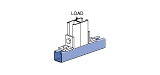
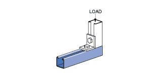
Bearing Loads
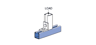


Standard 1-5/8" Wide Channel
Channel
Bearing Length 1-5/8" Maximum Allowable Load lbs
Bearing Length 1-5/8" Maximum Allowable Load lbs
Bearing Length 3-1/4" Maximum Allowable Load lbs
1-5/8" Solid/Slotted
13/16" Solid/Slotted
Beam Load Table
See Beam Load Tables
Loads in the Beam Load Tables for UNISTRUT® metal framing channel are given as a total uniform load (W) in pounds. For the more familiar uniform load (w) in pounds per foot or pounds per inch, divide the table load by the span.
Loads under the column headings of “Span / 180”, “Span / 240” and “Span / 360” are provided for installations in which deflection (sag) of the loaded UNISTRUT® channel must be limited. These ratios are standard engineering practice and, when applicable, are usually given by the Professional of Record or the Project Specifications. Actual deflection from these preset ratios equals the span (inches or feet) divided by the number 180, 240 or 360. When designing to one of these deflection limits, the allowed uniform load is generally less than the values under the column heading “Maximum Allowed Uniform Load”.
All 5 Notes below the beam load tables must be followed to obtain the final usable load on the channel. Failure to do so produces the wrong working load. These notes require adjustments to the Maximum Allowed Uniform Load for:
- Pierced Channel (if applicable)
- Unbraced Length
- Channel Weight
- Midspan Point Loads (if applicable)
Step #1: Determine Maximum Allowed Uniform Load from Load Table
Step #2: Multiple by the Applicable Pierced Hole Factor (if using a Beam Load Table for the solid channel)
- 0.95 for “KO”
- 0.90 for “HS” & “H3”
- 0.85 for "T", “SL” & “WT”
- 0.70 for “DS”
Step #4: Subtract Channel Weight
Step #5: Multiply by 50% for Midspan Loading (if Applicable)
The result after Step #4 is the net allowed total uniform load in pounds. The result after Step #5 is the allowed midspan point load.

 Continue modifying your quoted cart?